Acknowledgement of Inventory
Purpose
Before getting started, please verify your kit is complete.
Tools & Fixtures Needed
TOOLS
| Part Number | Vendor | Description | Qty |
|---|---|---|---|
| ATS8814VE | Aircraft Tool Supply | Rivet Puller Gun (Long Nose) | 1 |
| ATS8821V | Aircraft Tool Supply | Rivet Gun | 1 |
| NA | Amazon | Popcicle Sticks for Hysol Application | 500 |
| 24658 | Bolt Depot | 1/2" Step Bit | 1 |
| 28252 | Bolt Depot | Large Hose Clamps | 4 |
| DWDA/CX1230 | Drills and Cutters | #30 Drill Bit (12" Jobber) | 2 |
| DWDA/CX1240 | Drills and Cutters | #40 Drill Bit (12" Jobber) | 2 |
| KFD12 | Drills and Cutters | #12 Drill Bit | 5 |
| KFD30 | Drills and Cutters | #30 Drill Bit | 5 |
| KFD40 | Drills and Cutters | #40 Drill Bit | 5 |
| KFD1/4 | Drills and Cutters | 1/4 Drill Bit | 5 |
| KFD5/16 | Drills and Cutters | 5/16 Drill Bit | 5 |
| KFD3F7/32 | Drills and Cutters | 7/32 Drill Bit | 5 |
| DWRR1/4 | Drills and Cutters | 1/4" Reamer | 1 |
| DWRR3/16 | Drills and Cutters | 3/16 Reamer | 1 |
| DWRRCO3/8 | Drills and Cutters | 3/8 Reamer | 1 |
| DWRRCO5/16 | Drills and Cutters | 5/16 Reamer | 1 |
| ead200ms-11/21 | Ellsworth Adhesives | Manual Epoxy Gun (Option 1) | 1 |
| 807NC8 | Grainger | Drill | 1 |
| Any | Home Depot / Lowes | Tape Measure with 10ths | 1 |
| Any | Home Depot / Lowes | Cordless Drill | 1 |
| Any | Home Depot / Lowes | Set of Awls | 1 |
| Any | Home Depot / Lowes | Hand Rivet Gun | 1 |
| 24385 | Home Depot / Lowes | Waist Apron | 1 |
| 50519370 | MSC | Sand Paper | 1 |
| YA-DAP-1/8 | MSC Industrial | Replacement Blades for 1/8" Cogsdill Bit | 10 |
| YA-DAP-3/16 | MSC Industrial | Replacement Blades for 3/16" Cogsdill Bit | 5 |
| 64-Cgmp | Nicopress | Crimping Tool | 1 |
| 4942839 | Northern Tools | Knipex Pliers Set | 1 |
| 645-6-EACH | Pegasus Auto Racing | Cleco - Gold | 20 |
| 645-4-EACH | Pegasus Auto Racing | Cleco - Copper | 550 |
| 645-3-EACH | Pegasus Auto Racing | Cleco - Silver | 550 |
| 646-3/4-1.0 | Pegasus Auto Racing | Cleco - Clamps | 10 |
| YA-0125 | Penn Tool Company | 1/8" Cogsdill Bit or Texas In/Out | 2 |
| 720173 | RS Hughes | 1:1 Mixing Tubes - 10 pack | 1 |
| 079340-83128 | RS Hughes | Hysol EA 9460 | 1 |
| H-1343 | Uline | Cable Cutters | 1 |
| SUL DP2X 200-01-25-01 | www.gluegun.com | Pneumatic Expoxy Gun (Optoin 2) | 1 |
| 14844 | Yard Store | 3/16 Cogsdill Bit or Texas In/Out | 2 |
| 11094 | Yard Store | Cleco Pliers | 1 |
FIXTURES
Manual Overview
Purpose
This manual provides drawings, pictures, parts references, eDrawings access, and step-by-step instructions for the assembly, inspection, or service of a NXS Beaver Experimental Aircraft.
General Instructions
- Read the entire procedure before beginning work.
- Verify you have the required parts, tools, and drawings.
- Review all warnings, notes, and torque/fit requirements.
- Use the page navigation to move sequentially through the manual.
Featured Image / Product Picture
Related Resources
General Guidelines
Purpose
To construct your aircraft to the highest possible standard you should employ established aircraft engineering practices and safety precautions. The following guidance should be carefully read before you start work. If you need further information or guidance please consult your inspector or call NeXuS AEROspace who will be pleased to assist.
SAFE WORKING PRACTICES
All building operations should be undertaken with tools and equipment that are suitable and safe for the purpose. The improvised use of unsuitable equipment is potentially dangerous to the operator and will not give the best results. Check that all electrical and air tools are in good condition and that hoses and cables are undamaged. A suitably rated fuse or breaker should protect electrical equipment. It is strongly advised that a hand barrier cream is routinely used. Adhesives, solvents and fiberglass produce irritants to the skin. Surgical rubber gloves will also give adequate protection. The finishing scheme requires the use of acetone or methylethylketone (M.E.K.) as a thinning or solvent agent when applying the fabric cement and use other chemical thinners for fabric sealing and finishing. All these chemicals are highly aromatic and some contain substances that can be hazardous to health with prolonged exposure. The use of suitably protective breathing equipment together with eye protection is not regarded as optional. Always wear a mask for dust producing work and approved equipment for all spraying operations Ensure components are firmly clamped for drilling or hole clearance operations.
PARTS NUMBERING
Most fasteners are identified by their AN # or the manufacturers part #. Also, they are cross referenced on the Bill of Material to the appropriate F or W #. There are two Bill of Materials supplied. One is sorted by the manufacturer for ease in re-ordering in the U.S.A. The other is sorted by the Alpha # for ease in finding when referenced in the build manual. The parts with F&W #’s that are not AN #’s etc. should be stocked by part # for ease in locating during the build cycle. Although your kit will have an inventory check before delivery, your own checks will help you become familiar with the parts numbering system and the separate grouping of components according to their use.
CUTTING AND LAYOUT LINES
Cutting and layout lines on wood components should be made in pencil (medium hard grade) or fine line permanent marker. Scribers should only be used on cutting lines. Use a fine line permanent marker on fiberglass and metal. Use masking tape to mark out on surfaces where clear lines might otherwise be difficult.
HOLES
All holes must be marked out to give a minimum distance to an edge of two finished hole-size diameters from the center of the hole, e.g. 1/4” from the center of the hole for 1/8” diameter holes. It is recommended that holes marked out on metal components are ‘popped’ with an automatic centerpunch and pilot drilled undersize before final size drilling or use of a step cutter. When using a step cutter, proceed very cautiously and use the fastener to be fitted through the hole as a size gauge. It is recommended that holes in spar tubes and other critical areas are hand drilled for better control of the sizing and roundness.
DEBURRING AND HOLE COUNTERSINKING INSTRUCTIONS
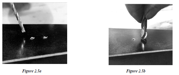
The instruction to deburr is used frequently throughout this manual. A burr is formed whenever you drill any material and is the ragged edge around the hole. In the left photo the hole on the left was drilled from the underside and the hole on the right from above. Note that a burr was formed in both cases. All drilled holes must be deburred because the presence of a burr will cause a bolt or rivet hole to have a stress raiser from which cracking can occur. Also, the fastener is bound to be a poor fit. Light burrs may be removed as shown in the right-hand photo but a proper deburring tool with its variety of cutters is much to be preferred.
All holes requiring countersinking should be cut with a countersink cutter of the correct included angle for the rivet or other fitting to be fastened through the hole. Do not use oversize twist drills for the purpose – they are not ground to the correct angle and will rarely produce a satisfactory countersink. Countersinking is not always easy to accomplish and should be practiced on scrap material before attempting cuts on components.
REAMING
Weld penetration and powder coating are two things that can decrease inside diameters of holes and bushings to the point where they need to be cleaned out before installing hardware. Hand parallel reamers (those with a small lead-in taper) are the preferred tools to clear holes. Also, it is better to use them with a hand tap wrench. Use of power tools can lead to bell mouthed holes, broken cutters and possible injury if they jam on weld penetration for example.
METAL PREPARATION AND CORROSION PREVENTION
Builders receive their aircraft powder coated unless ordered otherwise, it is important to inspect your aircraft even though the powder coating eliminates virtually any possibility of corrosion. Check for thin or bare spots in the powder coating. If there are any, simply prepare the area with a Scotch Brite pad, degrease it with acetone or methylethylketone (M.E.K.) and paint it with a matching color epoxy-based paint. All aluminum has an alkaloid coating that protects it from corrosion. It is important to take caution in the care and handling of aluminum. If the alkaloid coating is scratched, corrosion will form at scratch. Do not scratch aluminum until the time is needed for construction. Powder coated surfaces that will be epoxy bonded to other surfaces e.g. wing strut to spar brackets, must have the powder coating scuffed deeply before bonding. The coating can be scuffed using abrasive cloth flap wheels, abrasive cloth, and wet or dry abrasive paper. The scuffed surface should be left rough to ‘key’ the epoxy bond. Cut metal edges of brackets, spar tube ends etc should be dressed to a smooth surface finish using fine files and/or fine abrasive paper or abrasive cloth. Heavy cutting marks allow stress concentrations that often become the source of fatigue cracks. Where dissimilar metals meet, and the join does not have epoxy, a suitable barrier - e.g. Zinc chromate - must be used between the metals to prevent any contact between them. Please remember that this also applies to all bolts in the aluminum spars.
FASTENER RULES - All Fasteners should be (down, in, and back)
As a general rule all bolts and headed joint pins must be fitted with the heads uppermost (vertical applications) or forward (horizontal applications). In control runs this is absolutely mandatory because should a nut become detached and the bolt vibrate out, the control run catastrophically fails. All bolts and pins should be fitted with the specified type of nut or fastener. Self-locking nuts (composite inserts) as with all types of nuts should have at least 2 full threads of the bolt exposed when fully tightened. This type of nut may be used more than once provided adequate friction remains between the nut and mating thread. However, a new nut is always preferred as the safe option. It is strongly recommended that the bolts and other fasteners provided in the kit are retained for final assembly only and that spare items are obtained for the inevitable repeated fitting and removal of assemblies during construction.
PREPARING FOR BONDING
In order to achieve a maximum strength bond on aluminum alloys it must be thoroughly cleaned. Similar principles apply to bonding all other materials. Aluminum quickly accumulates an oxide layer when exposed to the air. Epoxy adhesives will not form an intimate bond with the underlying metal if oxide is present. As a general procedure, mark out the area to be bonded with a fine tip marker pen using the component as a template and extending the line about 1/4” beyond the edge of the component.
Carefully abrade the area with no coarser than 240-grit abrasive cloth leaving a crosshatched pattern on the surface. Fiberglass components should be similarly prepared. Do not clean until you are ready to glue, and then within 2 hours of final joint assembly clean the bonding area thoroughly with acetone or MEK (do not use any form of ‘oily’ solvent like petrol). The best method is to use strong industrial cleaning tissue paper soaked in solvent and continue wiping with fresh tissues until no discoloration appears on the surface of the tissue. Masking tape can be used on each side of the work to keep the area clean in the gluing process and to prevent scratching of surfaces outside of the gluing area. Wing ribs and other wood components should be lightly cleaned with fine grade sandpaper before epoxy bonding, applying fabric cement or other surface finishes.
MIXING AND APPLYING ADHESIVE
STEP 1: MIXING GLUE
Carefully mix the Hysol 9460 glue, according to the instructions on the can. Note; the can specifies equal measures by weight, however this not a critical point and by volume can be used. This is an epoxy type of glue; therefore, it will harden due to the catalytic action of the two components and will harden faster as the temperature rises. The glue must be mixed thoroughly on a hard surface and if it is ready before you are, you can delay the hardening by placing the glue in a freezer. Acetone will remove glue when still soft.
STEP 2: APPLYING GLUE
The glue is much easier to handle if it is squeezed from a heavy plastic bag with the tip cut off of one corner; for larger jobs an empty and thoroughly cleaned sealant cartridge may be used. Spread the glue in an even coating to the components to be bonded.
STEP 3: APPLY PRESSURE TO GLUE JOINTS
Bring the components together and apply slight movement to one component to expel any trapped air. Finally position the joint and apply moderate clamping pressure to consolidate the joint and prevent movement. Check each glue joint to be sure there is a fillet of glue all around the joint. Keep acetone and paper towels handy for cleaning up. Recheck the joint frequently and reshape the glue as necessary until it gets stiff enough to stay in place. Immediately recheck all dimensions before the glue sets up. To achieve neat filleting of the joint wait ½ to 1 hour after applying the adhesive; the glue will achieve the consistency of putty. Using a round ended instrument (e.g. a finger) and water or liquid soap, smooth and contour the surface.
STEP 4: ALLOW GLUE TO HARDEN
After rechecking the dimensions and positioning of the joint it is important to leave it alone for at least 12 hours before removing any clamps. Do not remove any holding device until pressure from your thumbnail will not dent the glue.
WORKING WITH DACRON COVERING
Your aircraft kit includes the covering materials to enable you to cover the structure and glue the fabric to your aircraft. It is recommended that if you are not previously experienced in the covering scheme you should purchase and study the company’s ‘How to Cover An Aircraft’ publication before starting this phase of construction. Covering is not difficult if you follow the guidance and do not rush at any stage of the process. The more careful and meticulous you are with your work the more you will be pleased with and proud of the results.
ELECTRICAL COMPONENTS AND WIRING
The choice of avionics and other electrical systems is left to the builder’s discretion. However, for safety reasons, all electrical wiring and components must be of a suitable gauge and rating for the intended purpose. Crimped terminal ends are to be preferred over soldered joints wherever possible and all terminals should be fitted with heat shrink or other suitable insulating and moisture resistant sleeving. Also, avoid excessive unsupported wiring runs by using appropriate strapping or clipping
SWAGED CABLE ENDS
Where cables have been swaged, the result must be proved to be secure. This may be done on or off the airplane, as applicable. There is a measurement in AR.43 for each size of nicopress sleeve. It is recommended that heat shrink sleeving over the crimped sleeve and cut cable end is used to protect all swaged cable ends. If a special purpose heat gun is not available an electric paint stripper gun may be used with care. A hair dryer does not produce sufficient heat to affect a proper shrink and should not be used.
LUBRICATION
It is recommended that on final assembly you lightly lubricate all metal bearing assemblies with anti-scuffing grease (e.g. molybdenum or lithium). Use rubber and nylon lubricant where applicable. You will be responsible for instrumentation, avionics, upgrades to upholstery, fabric sealant, UV-protection and final color scheme materials. The Superflight finishes are recommended because they are easy to apply and repair. You will also be responsible for general consumable items and materials e.g. acetone for cleaning, fine grit sandpaper, rags, heat shrink tubing, etc.
WORKING WITH TURNBUCKLES
When working with turnbuckles, e.g. on the rudder pedals, the manufacturer recommends that no more than three threads should be showing either side of the barrel. Turnbuckles should be set up such that in their initial setting the two ends are screwed into the barrel to a halfway point. To calculate this point, screw on the ends and wind them in until they won’t go any further; this is one extremity. Now wind them out until 3 threads show; this is the other extremity. Finally, set them to be halfway between the two positions. Turnbuckles have to be secured either with special wire locks (line up the groove marks on the end and on the barrel, insert the straight leg into the grooves and push until completely in then the catch end is inserted into the hole in the center of the barrel) or safety wired to prevent movement.
REMOVING POWDER COATING
We have found that spray gasket remover will easily take off powder coating. Tape off all areas that you do not want the powder coating removed and spray the areas that you do want removed. Wait a minute or two and you will see it bubble up, then wipe it off.
WORKING WITH ALUMINUM SHEETMETAL
It is common practice to debur all edges with suitable deburring tools. When working with clecos take care not to force the clecos in or out or damage could occur to the hole area. All holes are punched #40. Put a cleco into each hole, don’t skip any. Remove 1 at a time and drill to a #30. Replace with a #30 clecos, once all holes are filled with #30 clecos disassemble, debur and reassemble with #30 clecos. Remove 1 at a time and rivet. Any shortcuts here can result in a wavy surface.
Errors in the Manual or Improvement Recommendations
While we have tried to cover all aspects of the build but also realize that there will be errors and recommendations for improvement. Please send all errors and recommendations to NeXus AEROspace. Changes will be updated on the online system, so they can be seen by everyone.
Step-by-Step Instructions
Procedure
- Lay out all required components on a clean work surface.
- Inspect parts for damage, finish condition, and correct revision.
- Position the main bracket according to Drawing D-1001.
- Install support tubes and verify fit before tightening hardware.
- Torque all fasteners to specification listed in the hardware chart.
- Inspect alignment and verify free movement where required.
Hardware / Torque Data
- AN3 Bolt - 20 to 25 in-lb
- AN4 Bolt - 50 to 70 in-lb
- Use approved locking method where specified
Instructional Photos
Inspection Check
- All required hardware installed
- Correct orientation verified
- Torque applied and recorded
- No interference found during movement check
Inspection, Media, and External Links
Final Inspection Steps
- Verify all parts match the latest drawing revision.
- Confirm all inspection points are completed.
- Record serial number, date, and technician name if required.
- Attach sign-off documentation.
Pictures / Gallery
Important Links
Revision History
- Rev A - Initial release
- Rev B - Added updated drawing callouts
- Rev C - Revised torque table and inspection notes